
Amp Wiring Kit 101
Page 1 of 1

Amp Wiring Kit 101
![]() The Bishop Tue Jan 24, 2012 10:12 am
The Bishop Tue Jan 24, 2012 10:12 am
A Beginers Guide to Fitting a Basic Amp Wiring Kit. This was Fitted to The "Project Bender" Enjoy.
Please Note: This “How To” guide is designed for the beginner fitter, please ignore the obvious if you are experienced, but then again you won’t need to read this anyway. TB
As part of project bender, we wanted to pre fit an Amp Wiring Kit, although we are not going to be fitting an Amplifier or Sub Woofer, we decided that we would fit the kit anyway as it is a relatively cheap modification, and since we had already removed the interior, we could do this easily and neatly so no wires would show.
The kit we used is a basic off the shelf type, consisting of, Main power cable (Red with inline fuse holder), Negative earth cable (Black), Amp Remote cable (Blue), Phono Cable (Red and White ends) and Speaker wire (Twin Core). We won’t be using the speaker wire for this job, and so keep it for another build.
Main Power:
First thing we had to do was fit the Red Main Power cable. Please note the correct ends of the cable; although it is not a direction sensitive cable, the manufacture has kindly pre-fitted an inline fuse holder. The normal way to fit is with the fuse holder at the battery end of the cable.
You will need to find the Bulkhead (firewall) grommet, on the “bender” it is not easy to find. If you grab a torch and stick your head up the Near side (passenger) foot well just to the left of some underlay you will see a cable bundle coming out of the Grommet in the bulkhead (see pic).
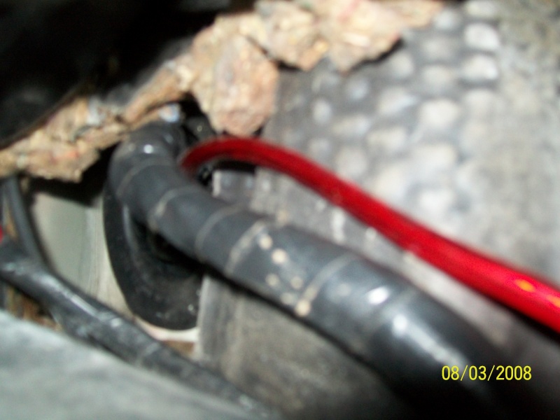
. The grommet is only soft rubber and you should be able to slip the power cable through alongside the main bundle that is already there. We however wanted to fit the Inline Fuse on the battery end, and so need to get to the other side of this grommet. For this next bit you will need a 3mm Allen key. Inside the Near Side Front Wheels Arch, are 6 or 7 short grub screws, remove these and the Arch liner will become loose enough to drop down and revel the inner arch. In the right next to the bulk head you will find a cable clip, holding the large cable bundle. If you follow it inwards you will come to the back end of the Bulkhead Grommet.
Take the long side of the Main Power Cable and start to feed it through the grommet, after about a foot of feeding, go into the near side foot well and pull the slack through. When you feel it tug go back to the engine bay. If the battery is removed you will see a small hole in the side wall of the engine bay. Feed the Cable up through this hole and pull through until the Inline fuse holder is in the battery compartment (see pic).

Secure this end of the cable and return to the Near Side Foot Well. Take the cable and start to feed it through the Cable Clips that run along the inner sill of the bodywork. When you reach the rear seats, there is a metal box section, feed the cable trough and then through the clips all the way up into the boot area (see pic).


Once in the boot Section, tie up the cable and place it out of the way while you do the rest of the job.
Amplifier Remote:
The Amp Remote cable is the Thin Blue one in the kit. One end will usually have a Bullet Clamp Connector fitted. This is the end to go to the head unit. From the Head unit or centre console, start to feed the loose end through and reach behind the centre console to pull the slack underneath. This is a good time to get out the Crimpers if you have a set, if not a pair of needle nose pliers will do. At the rear of the head unit is a large black connector, this is called the I.S.O. harness adaptor. This has two distinct sides; one side will have 8 coloured wires grouped in pairs, usually, purple, white, grey & green with a corresponding striped twin. This is the speaker side of the I.S.O. The other side will normally have 5 wires, Red (+) Black (-) Yellow (Memory) Orange (Constant) & Blue (Remote or Power Antenna). Strip the end of the blue wire to leave approx 10mm of bare wire, twist this and feed into the bullet connector on the end of your Amp Remote Cable. Use your Crimpers and make sure you have a tight fit.
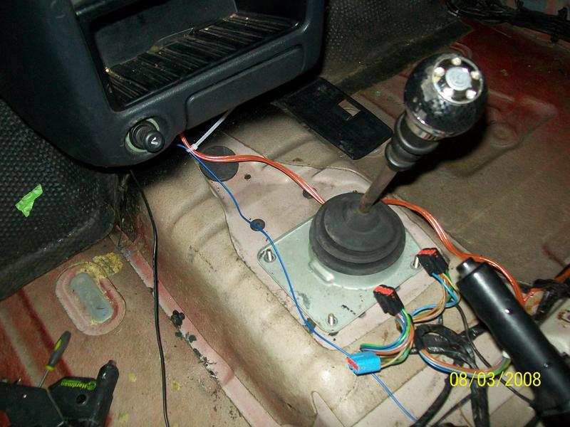
Now take the loose end of the cable and begin to feed it through the centre section of the floor (see pic).
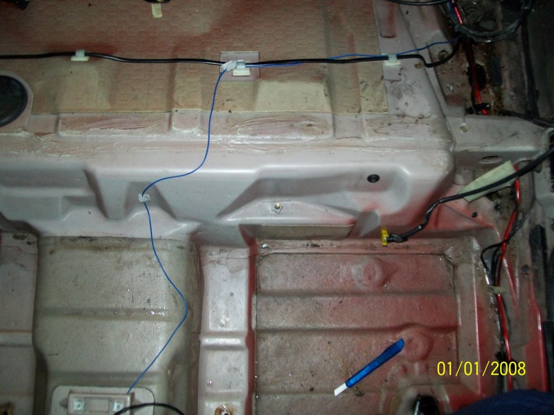
Once you reach the rear seats, follow the cables to the Nearside (passenger) and feed the cable up the same route as the Main Power cable you have already fitted. Again, once in the boot area, tie the cable up with the Main Power and leave until Later.
Phono Cable (a/v):
The Phono Cable is the twin core with one Red end and one White end. Again start at the Head Unit. Find the AV port on the back of the Head unit (or the SUB OUT in our case) plug the cable in to the colour coded sockets. Now feed the loose end down through the centre console, as you did with the remote cable. Run up the centre section, about where the hand break is, start to run the cable along the front of the driver’s seat mounts (see pic)


And then up along the cable clips on the inner sill, all the way to the boot section. Again, once in the boot Section, secure the cable out of the way until later.
Negative Earth Cable:
Take the Black Negative Earth cable. Ours had two connectors pre fitted, one large ring connector and one small ring connector. Have a look around the boot area (near to where you want to fit your amp) to see if there is an existing earth point. We didn’t have one so had to make one. Luckily we had a small hole in the body work, but you can always drill if you don’t. Get yourself a 10mm Bolt and Nut along with 3 washers. Around the earth hole, make sure that there is no paint on the panel, if there is, simply sand it off down to bare metal. Put a washer on the bolt, then the large ring connector, then a washer. Next put the bolt through the hole put the last washer on the bolt, then the nut and tighten.
Again secure the cable out of the way until needed (see pic)

Congratulations, you have now fitted your Amp Wiring kit to your Mk5 Escort XR3i. This guide can of course be used for other cars. All that is left now is to re-connect the battery and fit inline fuse to the power cable. Obviously connect the amp.
The most important thing to remember when fitting an amp kit is. Disconnect the battery, and run POWER & SPEAKER Cables down OPPOSITE SIDES of the car. If the power and speaker cables are next to each other they can cause a magnetic field which will create a buzzing sound from your sub.
Thanks for reading.
The Bishop.
Amp Wiring Kit:
Ford Escort XR3i Mk5 Cabby:
Ford Escort XR3i Mk5 Cabby:
Please Note: This “How To” guide is designed for the beginner fitter, please ignore the obvious if you are experienced, but then again you won’t need to read this anyway. TB
As part of project bender, we wanted to pre fit an Amp Wiring Kit, although we are not going to be fitting an Amplifier or Sub Woofer, we decided that we would fit the kit anyway as it is a relatively cheap modification, and since we had already removed the interior, we could do this easily and neatly so no wires would show.
The kit we used is a basic off the shelf type, consisting of, Main power cable (Red with inline fuse holder), Negative earth cable (Black), Amp Remote cable (Blue), Phono Cable (Red and White ends) and Speaker wire (Twin Core). We won’t be using the speaker wire for this job, and so keep it for another build.
Main Power:
First thing we had to do was fit the Red Main Power cable. Please note the correct ends of the cable; although it is not a direction sensitive cable, the manufacture has kindly pre-fitted an inline fuse holder. The normal way to fit is with the fuse holder at the battery end of the cable.
You will need to find the Bulkhead (firewall) grommet, on the “bender” it is not easy to find. If you grab a torch and stick your head up the Near side (passenger) foot well just to the left of some underlay you will see a cable bundle coming out of the Grommet in the bulkhead (see pic).
. The grommet is only soft rubber and you should be able to slip the power cable through alongside the main bundle that is already there. We however wanted to fit the Inline Fuse on the battery end, and so need to get to the other side of this grommet. For this next bit you will need a 3mm Allen key. Inside the Near Side Front Wheels Arch, are 6 or 7 short grub screws, remove these and the Arch liner will become loose enough to drop down and revel the inner arch. In the right next to the bulk head you will find a cable clip, holding the large cable bundle. If you follow it inwards you will come to the back end of the Bulkhead Grommet.
Take the long side of the Main Power Cable and start to feed it through the grommet, after about a foot of feeding, go into the near side foot well and pull the slack through. When you feel it tug go back to the engine bay. If the battery is removed you will see a small hole in the side wall of the engine bay. Feed the Cable up through this hole and pull through until the Inline fuse holder is in the battery compartment (see pic).
Secure this end of the cable and return to the Near Side Foot Well. Take the cable and start to feed it through the Cable Clips that run along the inner sill of the bodywork. When you reach the rear seats, there is a metal box section, feed the cable trough and then through the clips all the way up into the boot area (see pic).
Once in the boot Section, tie up the cable and place it out of the way while you do the rest of the job.
Amplifier Remote:
The Amp Remote cable is the Thin Blue one in the kit. One end will usually have a Bullet Clamp Connector fitted. This is the end to go to the head unit. From the Head unit or centre console, start to feed the loose end through and reach behind the centre console to pull the slack underneath. This is a good time to get out the Crimpers if you have a set, if not a pair of needle nose pliers will do. At the rear of the head unit is a large black connector, this is called the I.S.O. harness adaptor. This has two distinct sides; one side will have 8 coloured wires grouped in pairs, usually, purple, white, grey & green with a corresponding striped twin. This is the speaker side of the I.S.O. The other side will normally have 5 wires, Red (+) Black (-) Yellow (Memory) Orange (Constant) & Blue (Remote or Power Antenna). Strip the end of the blue wire to leave approx 10mm of bare wire, twist this and feed into the bullet connector on the end of your Amp Remote Cable. Use your Crimpers and make sure you have a tight fit.
Now take the loose end of the cable and begin to feed it through the centre section of the floor (see pic).
Once you reach the rear seats, follow the cables to the Nearside (passenger) and feed the cable up the same route as the Main Power cable you have already fitted. Again, once in the boot area, tie the cable up with the Main Power and leave until Later.
Phono Cable (a/v):
The Phono Cable is the twin core with one Red end and one White end. Again start at the Head Unit. Find the AV port on the back of the Head unit (or the SUB OUT in our case) plug the cable in to the colour coded sockets. Now feed the loose end down through the centre console, as you did with the remote cable. Run up the centre section, about where the hand break is, start to run the cable along the front of the driver’s seat mounts (see pic)
And then up along the cable clips on the inner sill, all the way to the boot section. Again, once in the boot Section, secure the cable out of the way until later.
Negative Earth Cable:
Take the Black Negative Earth cable. Ours had two connectors pre fitted, one large ring connector and one small ring connector. Have a look around the boot area (near to where you want to fit your amp) to see if there is an existing earth point. We didn’t have one so had to make one. Luckily we had a small hole in the body work, but you can always drill if you don’t. Get yourself a 10mm Bolt and Nut along with 3 washers. Around the earth hole, make sure that there is no paint on the panel, if there is, simply sand it off down to bare metal. Put a washer on the bolt, then the large ring connector, then a washer. Next put the bolt through the hole put the last washer on the bolt, then the nut and tighten.
Again secure the cable out of the way until needed (see pic)
Congratulations, you have now fitted your Amp Wiring kit to your Mk5 Escort XR3i. This guide can of course be used for other cars. All that is left now is to re-connect the battery and fit inline fuse to the power cable. Obviously connect the amp.
The most important thing to remember when fitting an amp kit is. Disconnect the battery, and run POWER & SPEAKER Cables down OPPOSITE SIDES of the car. If the power and speaker cables are next to each other they can cause a magnetic field which will create a buzzing sound from your sub.
Thanks for reading.
The Bishop.

The Bishop- The Boss

- Posts : 71
Join date : 2012-01-24
Age : 48
Location : Barry-Bay-Dos -

Page 1 of 1
Permissions in this forum:
You cannot reply to topics in this forum|
|
|